![]()
 Part 10-Blowout surface intervention methods: Descriptions of debris
removal techniques; special services like junk shots, hot tapping and freezing; and proven
methods of well capping
Martin J. Kelly, Jr., Partner, Boots & Coots, L. P.,
Houston
and
L. Flak, former Wright, Boots & Coots employee
This article reviews the physically demanding job of clearing away damaged wellheads, BOPs, rigs and platforms to allow surface control of a blowout. Basic special tools and techniques used in these efforts are explained. Capping equipment and installation steps are reviewed. Options of diverting blowouts and inducing bridging are noted. And snubbing on blowouts and the difficulties this presents are discussed.
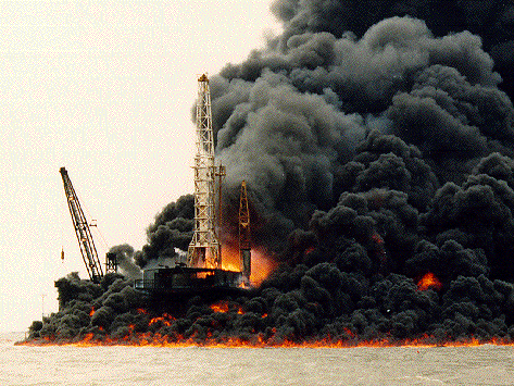
Figure above. This 1992 blowout in inland waters was capped while burning to limit pollution.
Experienced oilwell fire fighters bring more knowledge in the area of stopping leaks, removing dam aged equipment and controlling flow safely from a blowing well than in any other area. Many control options are available, as partially reviewed below. The key is selecting a control option that has the best chance of success, mini mum risk and viable economics. Time is also a major factor, as well conditions can change. The following discussion should be used as a basic guide to control options, methods and limitations.
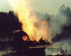
Fig. 27. This meltdown was the result of a voluntary well ignition of a deep H2S well
blowout in Mississippi (see photo on page 106, World Oil, October 1994).
The significant task of clearing away damaged rig or offshore platform components to expose the wellhead(s) is a first step on burning blowouts. Rig removal may also be required on non-ignited blowouts to allow removal/ replacement of defective BOPs or well heads. Only a few individuals have directed operations to remove destroyed rigs over burning blowouts. Even fewer have directed debris clearing operations on offshore burning blowouts.
Offshore challenges. Offshore efforts are based on exposing the wellhead(s). This involves clearing away upper decks and possibly melted remains of the rig and substructure. In Fig. 26, operations in 1992 by Boots & Coots on a burning barge rig in open bay waters behind a barrier island can be seen. The barge key-way was first cleared of melted rig debris. A major effort to cool the drilling barge to prevent further thermal deterioration while pumping it out, to float the drilling barge off the well, is illustrated. Water spray is directed at the barge and not the fire to maximize oil combustion and limit pollution. Oil containment booms are set around the work area and pumped off barge fluid and skimmed oil are directed into storage barges.
Well fires on massive offshore structures would require large semi-submersible-based derrick cranes to get sufficient deck height to match up elevation of the well bays. Derrick barges can be used on smaller structures. Major firefighting firms have crane hooks that work with large offshore cranes for debris clearing. Additional tools are generally custom fabricated at offshore sites using the extensive machine shop and welding/fabricating capabilities of the work vessels.
Cutting/removal techniques. Cutting away massive steel debris on large land rigs or offshore structures is sometimes required. Large fires will progressively melt away obstructing steel and at least partially expose the wellhead. If clearing is required, it can be done by various means, as described here.
Mechanically ripping, bending or fatiguing (repeated bending) away the debris with athey wagon and debris hook.
Swab line used as a reciprocated cable between winches is used to cut away wellheads or tubulars in areas and applications where only small cuts are required and high pressure abrasive cutting equipment is unavailable. Recently, a blowout in Venezuela required cutting away 6%-in. casing, 2Y-in. tubing and a polished rod with swab line. The cut required 18 hr to complete. This cut could have been made in less than 2 hr with a high pressure abrasive jet, but this equipment was not available in Eastern Venezuela.
Thermal lances or custom long cutting torches can be used to cut away debris on burning blowouts. In Fig. 28, Joe Carpenter with Boots & Coots can be seen preparing a long cutting torch which he used to cut away the kelly and rig floor beams under cover of water and reflective roofing tin on a 1992 blowout and fire. Very few individuals have the experience to do this safely.
Explosive cutting with shaped charges can be done on massive beams or tubular sections obstructing blowing wellheads. Shaped charges can be made in the field using raw C4 plastic explosive in fabricated holders. Point cuts, linear cuts and circular cuts can be fabricated by fire fighting explosive experts. Manufactured cutting charges are stocked by explosive manufacturers in some regions, but cannot be custom con figured to the application. These are generally the same companies that make oilwell perforating charges.
High pressure abrasive cutting with jet attachments that allow remotely operated cuts is the newest technology in firefighting. The technology was first successfully applied in the Kuwait fires. Halliburton markets this service to the oil field today. Smaller ultra-high pressure cutters are available out of industrial applications. Each system has particular applications and benefits. The principal benefit of the Halliburton system is the ability to mount the cutter on a boom for remotely applied cutting.
Meltdowns of land rigs can usually be removed using athey wagons, debris hooks and large dozers. Typically, at least two D8N dozers with winches are used. In one case of a large land rig meltdown on a deep Mississippi H2S blowout in 1985, Fig. 27, one D9N dozer walking an athey wagon with a hook into the debris and five stationary D8N dozers with 1-1/8 in. cable spooled off Cat 57 winches tied into the debris were required to skid off a massive accumulation of melted steel contained between two main substructure rig beams.
Debris clearing on burning wells is the most physically difficult firefighting operation and can take far longer than actual capping. Once debris is cleared and the well is exposed, final control operations can begin. The fire is generally not extinguished until the rig is cleared away. Firefighting operations were discussed in the previous article; as noted therein, the well may be capped while on-fire, based on pollution or H2S gas concerns.
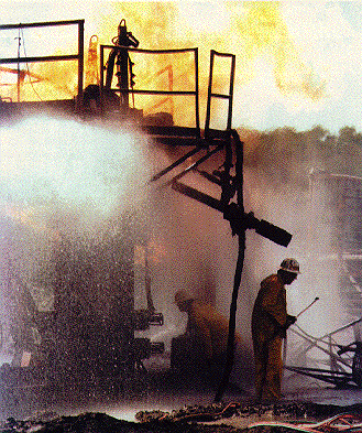
Fig. 28. Preparing for debris removal of fire-damaged equipment with a long cutting
torch on a small Texas land rig.
Specialized techniques have been designed by firefighters and service companies to achieve certain objectives such as plugging leaking connections, temporarily shutting off flow in lines, tapping into tubulars, cutting and stinging. Here are several examples.
Junk shots are used to plug leaking valves, flanges or BOPs. If an injection line can be tied into the well below the leak, this control option is possible. Time is critical as leaks are seldom stable and will erode out the leak path. The method involves loading a pump-in line near the well with shredded rope, rubber, nut hull, ball sealers and even golf balls to plug the flow path and allow conventional well killing operations to proceed. Higher mechanical strength fibers (Kevlar) and steel-rein forced rubber have been used to seal a leaking kelly cock valve (SIDP of 6,800 psi) through a hot-tap-drilled 1-in. hole. Stinger use requires junk shots to effect a seal around the stinger.
Freezing is used to place an ice plug within shut-in wells (within pipe, well heads or annulus) to allow removal, repair or replacement of wellhead equipment. Freezing has not been used to control a blowing well. Some inventors attempted to market devices using liquid nitrogen to freeze-off blowing wells in Kuwait, but simpler control methods were available. Difficulties were seen in maintaining a plug of frozen oil and brine while making extensive surface repairs to blown-up wellhead equipment.
The method usually uses dry ice to freeze water or fresh water-bentonite slurries. Methanol can be used with dry ice to get a lower temperature. As a 75% methanol/water mixture has a freeze temperature of some -200 deg. F, methanol water mixtures could be potentially cooled by liquid nitrogen and the cold methanol/water mixture circulated around the area to be frozen. This would allow control of the applied temperature to the steel-problems with low-fracture toughness in super cooled steels have been seen in nitrogen pumping service when pump rates exceeded heater capabilities and liquid nitrogen was pumped into wells.
Hot tapping and valve drilling equipment has been used on blowouts to allow pumping into wellheads, tubulars or fire-frozen valves. This equipment is available from most major fire fighting companies as part of their service capabilities. For a hot tap, a saddle clamp is installed around the tubular and a pack-off energized. Within a lubricator, a machine drill bit cuts through the tubular with pressure held slightly higher on the outside so positive indication that a hole has been made is seen. After the hole is cut, it can be reamed out to 1 in. Valve drilling machines are available to drill out frozen gates. Up to 3-in. holes have been drilled and larger hole sizes can be milled out.
Pneumatic cold cutters and high pressure abrasive cutters are used to strip away outer casing strings to expose inner strings for well capping. ABB Vetco Gray offers equipment to make vertical stripping cuts to split casing strings. Light linear shaped charges can also be bent around tubulars to make cuts. Pneumatic cold cutters, commonly used in the pipeline business, are used most frequently.
Stinging is a relatively rare control option that gained some fame in Kuwait, where 35% of the blowouts were con trolled using this method. The method involves snubbing a hollow conical device into the flow. A tee threaded above the device allows stinging the well with flow diverted vertically through the stinger and tee. The stinger is snubbed down into the blowout opening and the vertical flow path is shut off with a valve. Annular leaks between stinger and its rough fit to the blowout opening are sealed with junk shots to allow bullheading kill fluid into the well.
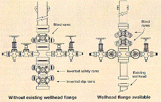
Fig. 29. Two types of well capping stacks.
New wellhead installation can be required if existing wellhead equipment is destroyed by the blowout. After exposing inner casing, a new wellhead (internal O-ring seal and external weld-on) is snubbed down over the inner pipe string and welded to the outer pipe string. An example would consist of a well with 13-3/8-in. surface casing and 9-5/8-in. protective casing with drill pipe dropped into the well and blowout flow out the 9-5/8 in. A casing head with hanger lock-down screws is snubbed through the flow and down over a 9-5/8 in. stub by use of a venturi tube.
A casing clamp is installed on the 9-5/8 in. stub above the casing head. Hydraulic jacks are used to pick up the 9-5/8 in. and re-tension the pipe. Tension can be directly calculated from hydraulic jack pressure. A wraparound casing hanger with integral pack-off is installed around the 9-5/8 in. and pushed into the slip bowl. The lock-down screws are run in to fully set the hanger and the hydraulic jacks are bled off. The 9-5/8 in. can then be trimmed to desired length with a pneumatic cold cutter, and the well can be capped with the assembly shown in Fig. 29.
In wells with only a single casing string, the wellhead is installed with slips locked in place around casing within the slip bowl and the entire well head is jacked up to tension the slips. A support base is then welded under the wellhead. (See related article, "How postcapping put Kuwait's wells back onstream," World Oil, January 1994, page 92.) Other capping or killing techniques are described here.
Capping stacks come in several configurations, with the stacks in Fig. 29 used most commonly. Blind rams are used above the diverter spool to divert flow. The extra blind ram provides a back-up, as erosion can occur in some high velocity flow streams. The long bell nipple lifts flow higher above the BOPs. The high weight of this capping stack helps stabilize it as it is moved into the flow stream. Once the stack is positioned over the flow and centered in the flow stream, it can be lowered into position over the stream. BOPs are sized based on mating flange size, or larger in high-volume flow streams.
Flow forces have caused unsupported capping stacks to be thrown away from the well; thus, the high weight of these stacks is actually more of a benefit than a liability. Even the massive capping stacks must be pulled or snubbed down over large blowouts or supported on a long stud bolt and spun over the flow. Spin or snub-on techniques are used by firefighters to stabilize and allow installation of capping equipment in flow streams.
Spin-on techniques use a long stud bolt run between the lower flange of the capping stack and the mating wellhead flange. The flanges are positioned 180¡ out of phase, very near one another, and one stud is dropped. The seal ring is tack welded into the lower flange of the capping stack or locked-in with set screws. The capping stack is then spun through the flow with the flange splitting the stream momentarily as it turns on the one stud into matching position. The capping stack is then lowered to bump up the flanges.
One limitation of this method is that there is a greater number of personnel near the flow stream as the capping stack is spun-on. Partial flow impingement starts the second the long stud is dropped as the spin axis for the larger bodies of the BOPs. This directs flow horizontally, with more horizontal flow as the flange splits the flow stream as it is spun on. Spinning is generally used on lower-velocity flow streams, smaller valve assemblies and confined capping spaces.
Snub-down methods consist of pulling down the cap ping stack by running two cables through the two flanges to be mated and using winches. The cables are run 180¡ apart through the wellhead flange, up through the capping stack flange and clamped together around the back of the capping stack. This process is underway in Fig. 30 on a recent blowout in South Texas with a nearly 300 deg. F surface flowing temperature. The two cables are winched in, drawing the two flanges together. This is the safer method of installing capping stacks but requires more support equipment, rig-up and operational control. It is the only method that should be used on large-bore, high-velocity flows.
Capping while burning was used recently on the blow out seen in Fig. 26 to limit pollution. A three-ram stack was used; this was developed and first used by the fire fighting contractor in Venezuela. This capping stack was positioned over flow out of tubing and lowered over the flow, as shown in Fig. 31. Note insulation on the BOPs, heat shielding on the capping boom and protective water spray. Most blowouts can be capped while burning.
Well diversion occurs before BOPs are closed, to prevent shocking the well. This means that diverter lines and choke manifolds are connected after the capping stack is in position. Large-bore diverter spools are used on high-rate blowouts with up to dual 7-7/16 in., 5-M outlets; and 6-1/8-in. bore valves are available out of Enterra's WELLCAT rental tool inventory. Use of large-diameter diverter lines is required when tubular condition is suspect, or the well is cratered and a minimum flowing pressure is desired.
If the blowout can be bullhead killed, then pumping is started and the well closed in. If well pressure build-up rate and magnitude is too high to safely bullhead, then pipe must be snubbed back to bottom to allow a circulated bottom kill. Sometimes wells are placed into production while extensive snubbing operations are undertaken or a relief well is drilled. Generally, the lowest sustainable flowing pressure, if water, oil and gas must be reliably separated, is about 150 psi.
Induced bridging can be used to kill some types of blowouts. Large diverter lines and even opening up the BOPs to drop flowing pressure has induced bridging on some wells. The principal risk is creation of a shallow bridge that only diverts flow underground.
Blowout snubbing or snubbing into a diverted blowout is very rare. Few snubbing supervisors have much experience in this type of operation. One of the most difficult operations is fishing dropped drill pipe or tubing to allow hydraulic reconnection to bottom or replacement with a kill string of proven integrity. Fishing with a snubbing unit within casing is generally successful. This was the case in the blowout shown in Fig. 30, as drill pipe had dropped only a few feet within the lower wellheads.
Problems with buckling, flow drag, produced formation solids, scale build up and
corrosion-erosion damage can be experienced. In open hole, flow out of a fish in enlarged
hole can make it nearly impossible to catch the fish as flow pushes the overshot away from
the top of the fish. Hook-wall guides, bent joints and even knuckle joints have not been
successful in catching blowing drill pipe in enlarged hole. Snubbing on drill pipe
blowouts dropped into open hole or on top of dropped fish found much deeper than expected
(fish parted and dropped beside itself has a low chance of success. A relief well may be
required to kill the blowout, because of the high mechanical risk of the snubbing
operation.
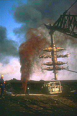 Fig.
31. Three-ram capping stack used with well burning to cap blowout shown in Fig. 26.
Fig. 30. Rigging up snub-down lines. Note extra BOP on bottom of capping stack to maintain diverter line elevation off of removed rig BOPs.
Relief wells. Advancements in technology and application engineering that make this
a primary blowout control option. Discussions include when the option is appropriate and
basic steps in design and execution.
![]() Next Article
Next Article
Bibliography
1. Flak, L., "How well control techniques were refined in
Kuwait,"World Oil, May 1992, pp. 72 82.
2. Flak. L. and Matthews C., "Blowout control: Response, intervention
and management, Part 9-Firefighting," World Oil, October 1994, pp. 101-108.
3. Wilson D., "How postcapping put Kuwait's wells back
onstream," World Oil, January 1994, pp. 92-94.
The authors
Martin J. Kelly Jr. is a partner with Boots & Coots, L.P., where he has worked as an oilwell firefighter and snubbing specialist since 1987. He begain his oil field snubbing career with Otis Engineering in 1967. From 1974 to 1987, he worked in snubbing up to the position of vice president operations for Best Hydraulic Workover, Inc. He designed and built the first snubbing unit with a lift capacity of more than 400,000 Ib., and he designed and used the first subsea snubbing unit. In Kuwait, he was a lead firefighter for Boots & Coots.
L. Flak is a former John Wright Company employee.