![]()
Blowout Modeling | Kill Modeling | Model Requirements | Inputs & Data Acquisition | Use in Well Planning | Next Article | |
 Part 5-Hydraulics Modeling. Matching known downhole well information with
surface flow characteristics of a blowout via computer allows selection of the most
efficient kill method
Paul Smestad and Ole B. Rygg, Hydraulics Specialists,
Well Flow Dynamics, Sandvika, Norway
John W. Wright, Blowout Advisor, John Wright Co., Houston
All well control design functions depend on construction of an accurate computer hydraulics model of the blowout at hand. Such a model incorporates all available downhole data on characteristics of the reservoir, well effluent, pressure, temperature etc., and factors influencing the surface flowpath of the blow. In turn, the hydraulics data allows development of a blowout model and, finally, a workable well kill model that will indicate the most efficient kill/control method to use.
The first step in blowout control is to survey and assess the situation. For complicated blowouts, this may be difficult and a poor survey may result in mobilization of excess or incorrect equipment and other resources.
On some projects, relief wells are started only after much time is spent on techniques that failed. A suspect contributor to such failures is lack of a good survey that prevents definition of an optimum control plan.
Proper hydraulic modeling matches known downhole well data to a description of the flowpath, identifying possible interpretations and eliminating those that cannot exist. Need for further data collection will also be indicated. Usually, more data is available than is immediately obvious. Portable computers now can handle complicated simulators, besides being used for presentations and plots of collected data. Hydraulics evaluations thus can be produced and analyzed onsite.
Even if data is limited, this exercise is useful since it can only improve understanding of the problem. For blowouts to surface, reasonable estimates of flowrate and type of liquid can be made by measuring size, height, width, color etc. of the fire. Exit conditions are indicated by direct observation of the wellhead area or via ROVs or minor excavation. Comparing well mechanical conditions with an estimate of formation productivity even allows simulation of wildcat blowouts. If more data can be gathered (pressure or temperature of flowing fluids, etc.) scenarios can be further narrowed.
Steady state conditions exist for blowout simulations and vertical flow models used in production engineering may be used for modeling. For gas wells flowing high rates of condensate, oil wells with high GOR, or high water flows, it is important to use PVT and two-phase flow correlations. Models also must be able to handle changes in flowpath, flow regimes and friction correlations. Often, engineers familiar with the area where the blowout occurs can be used to manipulate the model. For complex projects, blowout specialists supplying special hydraulics models and simulators may be called on.
Blowout modeling can provide surprisingly accurate results. In producing fields, good data may be available and kill operations can be planned with confidence. On underground blowouts, annulus and pipe pressures, temperatures, downhole flow measurements etc. may be obtainable. These parameters then can be matched in a simulation, improving the well kill operation.
Blowout simulations provide a range of possible kill simulations and resource planning. Better definition of blowout rates also help in defining pollution containment needs and possible diverter design for sales or flaring.
The main questions to be answered by well kill modeling are:
These can then be evaluated in terms of:
As a method is chosen and developed, detailed engineering can provide:
Hydraulics kill simulations are applicable to all blowouts. To describe the modeling procedure, dynamic kill modeling as applied to a relief well kill, or top kill through tubing or snubbing pipe, will be discussed.
Theoretical aspects of dynamic kills have been covered in writings by Blount and Soeiinahl, and others. They describe dynamic kill as a technique using flowing frictional pressure drop to supplement static pressure of the kill fluid being pumped up the annulus of the blowing well.
Water is often used in dynamic kills and is a good choice as an initial kill fluid if reservoir pressure is not far above hydrostatic. Water also is well adapted for evaluating communication and kill effectiveness, or while waiting on mud supplies. Known proper ties make it easy to model and predict behavior of a kill operation. Dynamic kill principles are applicable to both heavy and lighter fluids.
The modeling process can be split into two phases:
Establishing maximum rates, etc., can be done with steady state calculations. But dynamic (time based) calculations are needed to obtain kill volumes. Manually stepping a steady state simulator may also provide volumes. But they may not be accurate enough when required mud or specialty fluid volumes become large and logistics more critical.
When fluid weights and rates are determined, and allowances made for losses, a dynamic kill can be simulated based on equipment limitations (maximum pump rate, pressure and power) and pressure monitoring. Often, it is necessary to also compute pressure downhole to prevent exceeding fracture pressure, tubular burst pressures, etc.
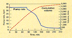
Results can be presented as tables or plots showing flow and pump rates, pressures etc. vs. time or cumulative volume, as best suited for a particular kill. Fig. 9 shows pump rate and cumulative volume vs. time for an off-bottom intersection of a gas blowout with a relief well. Plots with different scenarios/options then can be used to monitor kill effectiveness and losses. Together with monitoring of BHP when possible, plots can also be used to pick the correct model when uncertainties exist.2
Modeling results of blowout scenarios should be available as hard copies before the kill operation. Time seldom allows updating simulations during a kill, but comparing displays of collected data against models may be useful. All data such as pressures and rates should be collected on disk during kill operations for later analysis. At times more than one kill attempt may be needed due to uncertainties downhole and analysis of prior kill attempts may be required for success.

Fig. 9. Pump rate and cumulative volume pumped vs time for the dynamic kill of an
off-bottom intersection of a gas blowout and relief well.

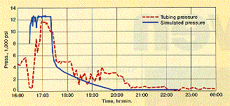
Fig. 10. Predicted vs actual pressures during a dynamic kill down tubing of an
underground blowout from a high pressure/temperature reservoir flowing through the tubing
and three casing strings.
The model required for well control planning and operations will depend on circumstances and the stage of the operation. Often, hand calculations or solving empirical equations via spread sheets or similar calculation methods may be sufficient, especially if correlated with experience from similar situations. An overview of well pressures, flowing and static pressure gradients, and ratings of pipe and equipment may be all that is needed in the case of predictable operations such as cap ping production wells. Equipment, supplies, people, etc., available on site may be insufficient and mobilization of more resources may be necessary. The ability to quickly assemble a logistical plan is important. Hydraulics modeling will define equipment needs by setting upper and lower limits on kill rates, pressures and volumes.
Often a well kill is described in terms of its main contributing element (dynamic kill, bullheading, volumetric kill, momentum kill, plugging, etc.). Calculations then can be made using a model or equations designed for the particular purpose. Results can be used to obtain densities, rates, pressures, volumes, etc. needed to regain static control of the well.
For example, maximum pressure transients to be expected when shutting in a well at surface will be the fluid gradient back to reservoir pressure. A PVT calculation with reservoir inflow modeling provides an upper limit to the answer. Such calculations can be performed by a reservoir engineer familiar with the area using software in daily use. This can be improved by dynamic calculations of pressures using a reservoir model with wellbore storage considerations, superimposing whatever fluid is pumped into the well etc.
Estimating an upper limit for the required rate for dynamic kill calculations can be made using published formulas or spreadsheet calculations for steady state flow, particularly if water is the kill fluid. As complexity or accuracy requirements increase, completeness of the modeling process becomes more critical.
Modeling requirements also become more demanding when equipment and supplies will not fit in space available, as offshore, or if more pumps or more fluid are needed than available, or if pressure ratings at surface or down hole are exceeded temporarily. It may then be necessary to tune weight, viscosity, pumping pressure etc. against each other and against time, indicating a dedicated dynamic well kill model will be required. This model should include all physical processes included in the control operation, such as fluid properties, friction, flow characteristics, interaction with changes in reservoir inflow behavior, etc. Dynamic means time-based, so pressure, flow and pump rate characteristics can change vs. time.
Importance of time-based models or simulators becomes obvious when considering, for example, buildup behavior when shutting in a well. For most reservoirs, BHP will be sharply drawn down during a blowout. And the initial buildup period can be used to pump kill fluid more efficiently than after pressure has increased. This effect will be the same in any kill operation.
Similarly, physical processes involved (friction, momentum, weight, etc.) all contribute to the kill process, so that kill requirements will be lower if all effects are considered together rather than one at a time.
Even the most sophisticated model will not work if input parameters are incorrect, or if the wrong options are chosen in actual calculations. Experience in such work is required, as well as a good quality control system including verification by engineers from several disciplines.
All models have limitations because experimental data may not exist to verify them for extreme conditions. Examples of modeling discrepancies are pressure losses for high rates through tubulars of non-Newtonian fluids such as muds. Models exist for these conditions, but they may not be applicable over the range found in well kill operations. Published equations taken out of context can end up being used outside of their applicable range if proper care is not exercised.
![]()
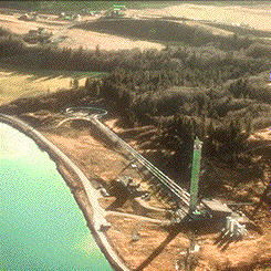
Fig. 11. Flowpath scenario in blowout was derived from production logging after a long, unsuccessful snubbing job. Relief well kill requirements were determined based on dynamic kill modeling and good match was made between predicted, actual kill rate used.
Traditional use of well hydraulic modeling is in the area of production well design and optimization, where accurate reservoir, fluid, pressure, temperature and flow characteristics are available. One might assume that modeling is difficult for a wildcat blowout, where minimal data is available. But even limited data may provide enough information to start defining equipment requirements.
Useful pressure and temperature data in this context can be obtained if access to the wellhead is available. Then, blowout flowpath and rates can be determined. For example, fluid flowing up tubing or drill pipe in a blowing well will have a different temperature from fluid flowing up the annulus for a given surface rate and pressure. If fluid composition can be determined, an accurate analysis can be made, especially for light fluids.
Reservoir pressure is an important parameter in these calculations, especially in wildcat blowouts. However, mudlog data can be used to analyze inflow behavior, pressure, depth and type of fluid.
Kicks that develop into blowouts often occur when work is focused on other operations such as workovers, etc. A pressure buildup that has gone unnoticed for some time may be reported as instantaneous, even though pit level, circulation rate and pressure data show it occurred over several minutes or hours. That results in a different inflow evaluation with corresponding decreases in required kill rates.
Pressure, temperature and other production logging techniques provide data useful for modeling underground blowouts.3 Fig. 11 shows a flow path scenario derived from production logging after a prolonged snubbing effort, and mechanical data. Coupled with dynamic kill modeling, relief well kill requirements were determined and a good match was made between predicted and actual kill rates.
Two categories of blowout contingency plans require hydraulic analysis:
Basic well design is adequately covered in the literature. Special applications may require kick analysis and evaluation of killing an under ground flow from the rig.3 This assessment is becoming more critical as operators try to cut costs by eliminating a casing string. Blowout contingency planning is needed for critical wells and structures such as offshore platforms to check on feasibility of killing wells and resources needed, especially for remote areas.
Well design may also be affected when drilling program changes reduce risk of a kick developing into a blowout.
Post analysis of kick handling is important to see if transient dynamic pressures or forces temporarily exceeded pipe pressure ratings or shoe strengths, in spite of static calculations indicating system integrity. This analysis can also help in determining if data used in the initial analysis was correctly interpreted.
Underground blowouts. The underground blowout is among the most common and the most
difficult to detect and kill. The next article presents the issues and methods employed in
underground blowout detection and control.
![]() Next Article
Next Article
Literature Cited
1. Blount E. M. and E. Soeiinah, "Dynamic kill: Controlling wild
wells a new way," World Oil, Oct. 1981, pp 109 126.
2. Rygg, O. B., and T. Gilhuus, "Use of a dynamic two-phase pipe flow
simulator in blowout kill planning," SPE, New Orleans, 1990.
3. Slungaard, C., and P Smestad, "Noise and temperature logging used
to determine underground blowout flowpath," SPWLA European Symposium, Budapest, 1990.
4. Wessel, Michael and Bryan A. Tarr, "Underground well control: The
key to drilling low-kick-tolerance wells safely and economically," SPE Drilling
Engineering, p. 250, December 1991.
5. Rygg O. B., P Smestad and .l. W Wright, "Dynamic two phase flow
simulator, a powerful tool for blowout and relief well kill analysis," SPE,
Washington, D.C., 1992.
The authors
Ole B. Rygg is a hydraulic specialist with Well Flow Dynamics, a Norwegian petroleum engineering firm specializing in multi phase flow simulations, particularly with respect to blowout controL He has worked with flow modeling at the University of Oslo since 1983, and at the Institute for Energy Technology, Kjeller, Norway. He holds a PhD in Fluid Mechanics from the University of-Oslo.
Paul Smestad is a petro leum engineer, specializing in blowout hydraulics and data acquisition. He started his career with Schlumberger in 1977, 6 working as field engineer and interpretation spe cialist in the Middle East, South America, and Europe. He joined Saga Petroleum in 1984 where he was manager-formation evaluation prior to joining Well Flow Dynamics in 1992. He holds a B. Eng degree from Sheffield University. John W. Wright's biography appeared in Part 1 of this series. Please see page 78, November 1993, World Oil.